sewing machine parts and functions pdf

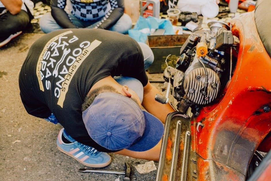
Understanding the intricate components of a sewing machine unlocks a world of creative potential, enabling precise fabric manipulation and durable seam construction.

Essential for both beginners and experienced sewists, familiarizing yourself with the machine’s anatomy—from the spool pin to the feed dogs—is paramount.

Detailed parts lists and service manuals, often available as PDFs, provide invaluable insights into each component’s role and proper maintenance procedures.

These resources showcase diagrams illustrating the interplay between parts, ensuring efficient operation and longevity of your sewing machine investment.

Mastering these fundamentals empowers you to troubleshoot issues, perform repairs, and ultimately, elevate your sewing projects to professional standards.

Understanding the Importance of a Sewing Machine Manual

A sewing machine manual is far more than just a collection of instructions; it’s the definitive guide to understanding your specific machine’s capabilities and intricacies. Crucially, it contains detailed parts lists, often available as downloadable PDFs, showcasing every component from the spool pin to the feed dogs, complete with diagrams.

These manuals are essential for identifying parts during maintenance or repair, preventing incorrect replacements that could damage the machine. Furthermore, they outline proper usage, ensuring safety and optimal performance; Ignoring the manual can lead to improper threading, incorrect stitch selection, and even mechanical failures.

The manual also details recommended attachments and accessories, expanding the machine’s functionality. It emphasizes intended use and precautions, safeguarding both the user and the equipment. Accessing a PDF version allows for convenient searching and referencing, making it an indispensable resource for any sewist, regardless of experience level. Ultimately, the manual unlocks the full potential of your sewing machine.

Overview of Common Sewing Machine Types

Sewing machines exhibit diverse designs tailored to specific needs, yet share fundamental parts detailed in accompanying manuals, often accessible as PDFs. Mechanical machines, the traditional workhorses, rely on manual operation and robust construction, showcasing visible components like the handwheel and belt.

Electronic machines introduce computerized controls for stitch selection and speed, enhancing precision and efficiency. Sergers, or overlock machines, specialize in finishing raw edges, utilizing multiple threads and unique components like loopers; Industrial machines, built for heavy-duty tasks, feature powerful motors and reinforced parts.

Understanding these distinctions is crucial when referencing parts lists and diagrams within a manual. Regardless of type, the core functions—thread delivery, needle motion, and fabric feeding—remain consistent. PDF manuals provide model-specific information, ensuring accurate identification of parts and proper maintenance procedures for each machine type.

Essential Sewing Machine Parts

Core components—spool pins, bobbins, needles, presser feet, and feed dogs—work harmoniously, detailed in parts lists and service manuals (often PDFs).

These elements facilitate thread handling, fabric clamping, and precise stitching, forming the foundation of sewing machine functionality.

Spool Pin and Thread Guides

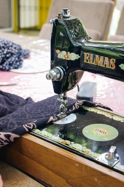
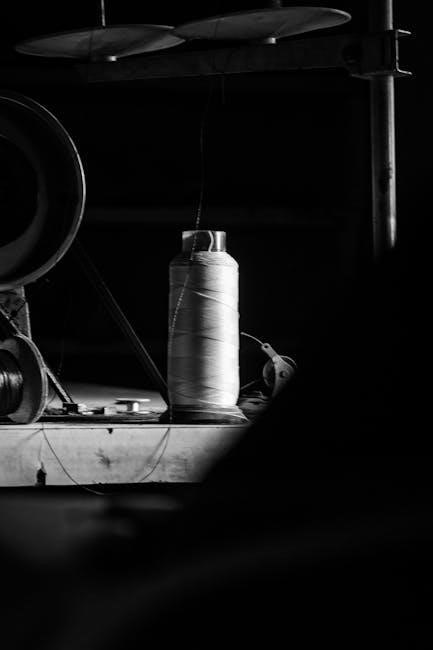
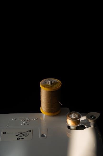
The spool pin, a seemingly simple component, is crucial for managing the supply of thread during sewing operations, as detailed in many sewing machine parts diagrams and PDF manuals;

Its primary function is to securely hold the spool, allowing it to unwind smoothly and consistently without tangling or snagging, which would disrupt the stitching process.

Thread guides, often integrated into the machine’s casing, work in tandem with the spool pin to direct the thread along the correct path towards the needle.

These guides minimize friction and ensure proper tension, vital for creating balanced and aesthetically pleasing stitches;

Variations exist; some machines feature retractable or adjustable spool pins to accommodate different spool sizes, while others utilize multiple thread guides for complex threading patterns.

Proper threading, following the machine’s manual, is essential for optimal performance, and understanding the spool pin and thread guide system is the first step towards achieving this.

Referencing a parts list PDF can help identify specific components and their correct placement, ensuring smooth and efficient thread delivery.

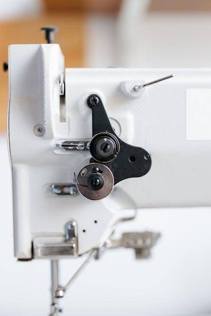
Bobbin Winder Spindle

The bobbin winder spindle is a dedicated mechanism responsible for transferring thread from the spool onto the bobbin, a critical step before commencing sewing, as illustrated in sewing machine parts diagrams and PDF manuals;

This spindle engages with a rubber tire or belt, driven by the machine’s motor, to rotate the bobbin at a controlled speed, ensuring even winding.

Proper bobbin winding is essential for consistent stitch quality; an unevenly wound bobbin can lead to tension issues and skipped stitches.

Most machines feature an automatic stop mechanism that disengages the winder once the bobbin is full, preventing overfilling and potential damage.

The spindle often has adjustable settings to accommodate different bobbin sizes and thread types.

Consulting your machine’s manual, often available as a PDF, provides specific instructions on engaging and disengaging the bobbin winder, as well as troubleshooting common issues.

A parts list PDF can aid in identifying and replacing a faulty bobbin winder spindle, ensuring continued smooth operation.

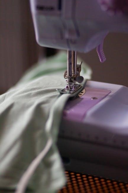
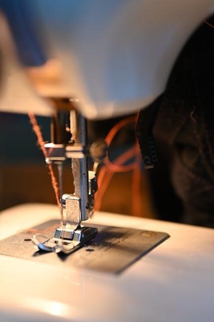
Needle and Needle Clamp

The needle, a fundamental component, pierces the fabric, forming the stitch when combined with the bobbin thread, as detailed in sewing machine parts diagrams and PDF manuals.

Needles vary in size, type, and point shape, selected based on fabric weight and weave; a universal needle suits many fabrics, while specialized needles exist for knits, leather, and denim.

The needle clamp securely holds the needle in place, ensuring it remains vertical during operation; it’s crucial to tighten the clamp firmly, but not excessively, to avoid breakage.

Regular needle replacement is vital, as dull or damaged needles can cause skipped stitches, fabric damage, and even machine malfunction.

A parts list PDF will show the correct needle system for your machine model.

Always refer to your machine’s manual, often a downloadable PDF, for proper needle insertion and clamp tightening procedures.

Incorrect installation can lead to needle breakage and potential injury.

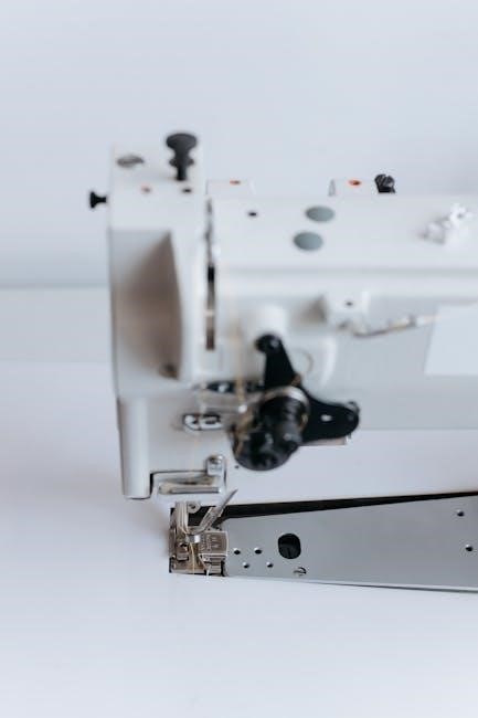
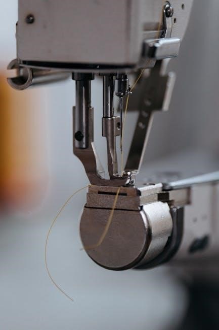
Presser Foot and Shank

The presser foot maintains consistent fabric tension against the feed dogs, crucial for even stitch formation, as illustrated in sewing machine parts diagrams and PDF manuals.

Various presser feet cater to specific tasks: a standard foot for general sewing, a zipper foot for close-to-edge stitching, and a buttonhole foot for precise buttonholes.

The shank connects the presser foot to the presser bar, allowing for vertical movement; it’s a vital link in the stitching process.

Adjusting presser foot pressure is essential for different fabric types; lighter fabrics require less pressure, while heavier fabrics need more.

A parts list PDF will detail compatible presser feet for your machine.

Proper attachment and alignment of the presser foot are critical for optimal performance.

Refer to your machine’s manual, often available as a PDF, for detailed instructions on changing and adjusting the presser foot and shank.

Feed Dogs and Drop Feed Mechanism

Feed dogs, located beneath the presser foot, are toothed metal components that advance the fabric during sewing, ensuring consistent stitch length, as detailed in sewing machine parts PDFs.

Their rhythmic movement, coordinated with the needle, pulls the fabric forward after each stitch, creating a neat and even seam.

The drop feed mechanism allows the feed dogs to be lowered, disengaging their fabric-feeding action.

This feature is essential for free-motion quilting, darning, and embroidery, where the user controls fabric movement.

A service manual PDF will illustrate how to engage and disengage the drop feed.

Maintaining clean feed dogs is crucial; lint and debris can hinder their movement and affect stitch quality.

Refer to your machine’s manual, often a downloadable PDF, for specific instructions on cleaning and adjusting the feed dogs and drop feed mechanism.

Key Functional Components

Essential operational elements—the handwheel, power switch, motor, belt, and tension system—work harmoniously to drive the sewing process, as PDFs explain.

Understanding these components, detailed in service manuals, is vital for efficient sewing and troubleshooting any operational issues.

Operating Control (Handwheel & Power Switch)

The operating control, encompassing both the handwheel and the power switch, forms the primary interface for controlling the sewing machine’s functionality, as detailed in comprehensive parts and service manuals often available in PDF format.

The handwheel allows for precise, manual control of the needle’s position, crucial for intricate work, starting/stopping at specific points, and carefully navigating corners or curves.

Rotating the handwheel clockwise lowers the needle, while counter-clockwise raises it; this manual override is invaluable for delicate fabrics or complex patterns.

The power switch, typically a simple on/off mechanism, activates the motor, initiating the automatic sewing process.

Modern machines may feature variable speed control integrated with the power switch, offering greater precision and adaptability for different materials and techniques.

PDF diagrams often highlight the location and operation of these controls, emphasizing their importance in achieving accurate and consistent stitching.

Proper understanding of both the handwheel and power switch is fundamental for safe and effective operation of any sewing machine.

Motor and Flywheel

The motor and flywheel constitute the powerhouse of a sewing machine, converting electrical energy into the mechanical motion necessary for stitching, as illustrated in detailed parts lists and service manuals often found as PDFs.

The motor, typically electric, drives the flywheel, a heavy wheel connected to the machine’s internal mechanisms.

The flywheel’s inertia smooths out the motor’s power delivery, ensuring consistent and even stitching speed, preventing jerky movements.

Older machines may utilize a treadle mechanism, where foot power rotates the flywheel, eliminating the need for an electric motor.

PDF diagrams frequently showcase the motor’s mounting and wiring, alongside the flywheel’s connection to the crankshaft.

Maintaining proper motor speed and flywheel balance is crucial for optimal performance and longevity.

Regular lubrication, as outlined in the machine’s manual, ensures smooth operation and prevents overheating of the motor components.

Belt and Tension System

The belt and tension system are critical for transferring power from the motor to the machine’s working parts, detailed in sewing machine parts lists and service manuals available as PDFs.

Typically, a V-type (35V) or O-type (1041) belt connects the motor’s pulley to the flywheel’s pulley, transmitting rotational force.

Proper belt tension is paramount; too loose, and power transfer is inefficient, causing skipped stitches, while too tight strains the motor and bearings.

The tension system, including tension discs and springs, regulates the thread flow, ensuring balanced stitch formation.

PDF diagrams illustrate belt routing and tension adjustment mechanisms, vital for maintaining consistent stitch quality.

Adjusting the tension compensates for different thread types and fabric weights, preventing looping or puckering.

Regular inspection and replacement of worn belts, as per the manual, are essential for reliable operation and preventing machine damage.

Oil Pump and Lubrication System

The oil pump and lubrication system are fundamental to a sewing machine’s longevity, meticulously detailed in downloadable PDF parts lists and service manuals.

These systems deliver oil to critical moving parts – the needle bar, shuttle, and connecting rods – minimizing friction and wear.

Components include the oil pump itself, oil pipes (like the 22T8-013D for the upper shaft), and oil reservoirs.

Oil flows through channels and wicks, ensuring consistent lubrication even during high-speed operation.

PDF diagrams clearly illustrate the oil flow paths and the location of oiling points, crucial for proper maintenance.

Covers, such as the 15WF4-004 for the oil pump, protect these components from dust and debris.

Regular oiling, following the manufacturer’s recommendations in the manual, prevents seizing and extends the machine’s lifespan.

Advanced Parts & Mechanisms

Detailed PDF manuals showcase complex systems like four-thread overlock stitches, V-type/O-type belts (35V, 1041), and specialized oil pump components.

Understanding these advanced mechanisms requires careful study of exploded diagrams and parts lists for optimal performance.

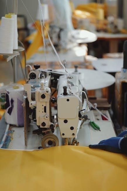
Four-Thread Overlock Stitch Components

The four-thread overlock stitch, a cornerstone of professional garment construction, relies on a precise interplay of specialized components detailed within comprehensive sewing machine parts PDFs.

These manuals illustrate the function of the upper and lower loopers, crucial for forming the interlocked stitches that prevent fabric fraying and provide stretch.

The feed dogs, working in concert with the loopers, advance the fabric evenly, ensuring consistent stitch formation.

Differential feed, a key feature of overlock machines, is controlled by separate feed mechanisms, allowing for adjustments to prevent puckering or stretching of delicate fabrics.

Tension discs regulate the thread flow to each looper, maintaining balanced stitch integrity.

The stitch finger guides the fabric path, ensuring proper alignment with the loopers.

Detailed diagrams within the PDF highlight the precise positioning and interaction of these parts, enabling accurate assembly and troubleshooting.

Proper lubrication of these components, as outlined in the manual, is vital for smooth operation and longevity.

Understanding these intricacies empowers sewists to achieve professional-quality overlock seams.

V-Type and O-Type Belts (35V, 1041)

Sewing machine operation heavily relies on the efficient transfer of power from the motor to the machine’s mechanisms, a task primarily handled by belts – specifically V-type (35V) and O-type (1041) belts.

Detailed parts lists and service manuals, often available as PDFs, illustrate the distinct characteristics and applications of each belt type.

V-belts, characterized by their trapezoidal cross-section, offer superior grip and power transmission, ideal for heavier-duty machines.

O-belts, with their circular profile, provide quieter operation and are often found in lighter-duty models.

The PDF diagrams showcase proper belt installation and tensioning procedures, crucial for preventing slippage and ensuring optimal performance.

Correct belt tension is paramount; too loose, and power transfer is compromised; too tight, and it strains the motor and bearings.

Regular inspection for wear and tear, as detailed in the manual, is essential for preventing unexpected breakdowns.

Understanding these belt specifications and maintenance guidelines ensures smooth and reliable sewing machine operation.

Covers and Oil Pump Components (15WF4-004, 22T8-006)

Maintaining proper lubrication is vital for the longevity and smooth operation of any sewing machine, and the oil pump system plays a crucial role in this process.

Parts lists and service manuals, frequently found as PDFs, detail the components of this system, including covers (15WF4-004, 22T8-006) and the pump itself.

These covers protect the delicate oil pump mechanism from dust and debris, ensuring consistent and reliable lubrication.

The PDF diagrams illustrate the precise placement and securing of these covers, preventing contamination and maintaining optimal pump function.

Regular inspection of the oil pump and its components, as outlined in the manual, is essential for identifying potential issues.

Proper oil levels and pump operation guarantee that all moving parts receive adequate lubrication, reducing friction and wear.

Understanding the function and maintenance of these components, guided by the manual, contributes to a longer machine lifespan.

Oil Pipe for Upper Shaft (22T8-013D)

The oil pipe, identified as part number 22T8-013D, is a critical component in the lubrication system of many sewing machines, specifically directing oil to the upper shaft.

Service manuals and parts lists, often available in PDF format, provide detailed diagrams illustrating the pipe’s routing and connection points.

This pipe ensures that the upper shaft bearings receive adequate lubrication, minimizing friction and preventing premature wear and tear.

A damaged or blocked oil pipe can lead to insufficient lubrication, causing the machine to operate noisily or even seize up.

The PDF documentation outlines the correct installation procedure, emphasizing the importance of a secure fit to prevent oil leaks.

Regular inspection of the oil pipe for cracks, kinks, or blockages is recommended as part of routine maintenance.

Replacing a faulty oil pipe with the correct part (22T8-013D) restores proper lubrication and extends the machine’s operational life.

Decoding Sewing Machine Diagrams

PDF manuals contain essential diagrams; parts lists detail components, while schematics illustrate assembly and function.

Locating parts within these visuals requires understanding symbols and referencing the accompanying parts list for identification.

Reading a Parts List

A sewing machine parts list, frequently found within a service manual PDF, is a crucial resource for identification and ordering replacements.

Typically organized numerically or alphabetically, each entry corresponds to a specific component of the machine, accompanied by a part number.

These numbers are universally recognized by sewing machine parts suppliers, ensuring accurate ordering and compatibility.

The list often includes a brief description of the part, its quantity required per machine, and sometimes, diagrams illustrating its location.

Understanding the list’s structure is key; cross-referencing with the exploded view diagrams within the manual is essential for visual confirmation.

Pay close attention to model-specific variations, as part numbers can differ even between similar machines.

Carefully review the list before disassembling your machine, noting the orientation and placement of each part for successful reassembly.

Accurate interpretation of the parts list minimizes errors and streamlines the repair process, saving time and frustration.

Understanding Schematic Diagrams

Schematic diagrams, commonly found within sewing machine service manuals in PDF format, represent the machine’s internal workings using symbolic representations of parts.

Unlike exploded views, schematics prioritize functional relationships rather than precise visual depiction, illustrating how components interact.

Lines indicate connections – mechanical linkages, electrical circuits, or fluid pathways – crucial for understanding operation.

Symbols represent specific parts; learning these symbols is vital for deciphering the diagram’s information.

Tracing the flow of power or motion through the schematic reveals the sequence of events during a sewing cycle.

These diagrams are invaluable for troubleshooting, pinpointing the source of malfunctions by following the affected pathway.

Referencing the parts list alongside the schematic allows identification of components within the diagram’s symbolic representation.

Mastering schematic reading unlocks a deeper understanding of the machine’s complex mechanisms and facilitates effective repairs.

Locating Parts in a Manual

Sewing machine manuals, often available as comprehensive PDF documents, typically feature detailed parts lists and diagrams for easy component identification.

These lists are usually organized numerically or alphabetically, corresponding to reference numbers on exploded view diagrams.

Begin by identifying the model number of your machine, ensuring you’re referencing the correct manual and parts list.

Locate the section dedicated to parts diagrams, often categorized by machine assembly – head, bed, or motor.

Cross-reference the part you need with the diagram, noting its corresponding reference number.

Then, find that number on the parts list to determine the official part name and number for ordering replacements.

Some manuals include a parts index, allowing direct lookup by part name, streamlining the identification process.

Digital PDFs often offer search functionality, enabling quick location of specific parts or keywords within the manual.

Safety and Maintenance

Prioritize safety by adhering to the manual’s precautions, utilizing recommended attachments, and understanding the machine’s intended use for optimal performance.

Regular lubrication, as detailed in the PDF, extends machine life, while proper handling prevents accidents and ensures consistent sewing quality.

Recommended Attachments and Accessories

Expanding your sewing capabilities relies heavily on utilizing the correct attachments and accessories, often detailed within your sewing machine’s PDF manual.

Essential accessories include a variety of presser feet – a zigzag foot for decorative stitches, a buttonhole foot for precise buttonholes, and a zipper foot for navigating close seams.

Bobbin cases, needles in assorted sizes, and thread spools are fundamental consumables, while seam rippers and lint brushes aid in maintenance and error correction.

Specialty attachments, like gathering feet or edge stitching feet, unlock advanced techniques, enhancing project versatility.

The manual’s parts list will specify compatible accessories for your specific model, preventing damage and ensuring optimal performance.

Investing in quality accessories, guided by the PDF documentation, elevates your sewing experience and unlocks a wider range of creative possibilities.

Always refer to the manual for proper installation and usage instructions to maximize the benefits of each attachment and accessory.

Intended Use and Precautions

Your sewing machine, as outlined in its accompanying PDF manual, is designed specifically for fabric-related sewing applications; deviating from this intended use can cause damage.

Crucially, the manual emphasizes using only manufacturer-recommended attachments and accessories, ensuring compatibility and preventing mechanical failures.

Never attempt to sew materials not intended for sewing machines, such as leather or excessively thick fabrics, without appropriate modifications and tools.

Always disconnect the power supply before performing any maintenance, including changing the needle or cleaning the bobbin area, to avoid electrical shock.

Keep fingers and other body parts clear of the needle and moving parts during operation, adhering to all safety warnings detailed in the manual.

Regular lubrication, as described in the PDF, is vital for smooth operation and preventing wear and tear; improper lubrication can lead to malfunctions.

Prioritize safety and follow the manual’s precautions to ensure a long and productive life for your sewing machine.

gogo scooter repair manual

Gogo Scooter Repair Manual: A Comprehensive Guide

This manual details Gogo scooter operation, safety, and maintenance․ It covers battery care, charging, electrical diagnostics, and component identification;

Gogo scooters, often categorized as travel or mobility scooters, represent a significant advancement in personal transportation for individuals with limited mobility․ These devices, like those from Pride Mobility, are designed to provide independence and enhance the quality of life for users․ Understanding the core functionality and intended use of a Gogo scooter is paramount before attempting any repair or maintenance․

These scooters are typically employed for indoor and outdoor use on smooth, even surfaces, offering a practical solution for navigating shopping centers, airports, and other public spaces․ The travel scooter is specifically intended for individuals capable of operating the device while seated․ Proper operation, as outlined in the owner’s manual, is crucial for safety and longevity․

This guide aims to provide a comprehensive resource for owners and technicians alike, covering everything from basic battery maintenance to complex electrical system diagnostics․ Familiarity with the scooter’s service manual and adherence to safety precautions are essential throughout the repair process․

Understanding Scooter Classifications: Ago vs․ Bgo

While seemingly unrelated to scooter repair, understanding the “Ago” and “Bgo” classifications, originating from a different context – nightlife entertainment – highlights the importance of accurate information․ This distinction, though not directly applicable to scooter mechanics, underscores the potential for misconstrued terminology and the need for clarity when discussing scooter components and repairs․

In the referenced context, “Ago” denotes performers requiring skill (dance, performance), while “Bgo” represents roles focused on interaction․ Applying this concept to scooters, we can draw a parallel: some repairs require specialized knowledge (electrical systems – “Ago”), while others are more straightforward (tire changes – “Bgo”)․

This analogy emphasizes that not all Gogo scooter repairs are equal in complexity․ A thorough understanding of the scooter’s manual and the specific issue at hand is vital․ Attempting complex repairs without proper training or tools can lead to further damage and safety hazards․ Always prioritize safety and consult a qualified technician when necessary․

Safety Precautions Before Repair

Prior to commencing any Gogo scooter repair, stringent safety measures are paramount․ Disconnect the battery immediately – this prevents accidental activation of the motor or electrical shocks․ Refer to the manual for specific battery disconnection procedures․ Ensure the scooter is parked on a level, stable surface, and engage the parking brake․

Wear appropriate personal protective equipment (PPE), including safety glasses to shield your eyes from debris, and gloves to protect your hands․ Avoid working on the scooter in wet conditions, as water and electricity pose a significant hazard․ Be mindful of pinch points and moving parts during disassembly․

Never attempt repairs you are not qualified to perform․ Improper repairs can compromise the scooter’s safety features and lead to injury․ If dealing with the electrical system, exercise extreme caution․ Consult a qualified technician for complex issues․ Remember elevator safety – avoid repairs in elevators!

Essential Tools for Gogo Scooter Repair

Successfully repairing a Gogo scooter necessitates a specific toolkit․ A basic set includes a socket wrench set, adjustable wrench, and various screwdrivers (Phillips and flathead) – essential for disassembly and reassembly․ A multimeter is crucial for electrical system diagnostics, testing voltage and continuity․ Pliers, including needle-nose and cutting pliers, are invaluable for manipulating wires and connectors․

For tire maintenance, a tire pressure gauge and tire repair kit are necessary․ A crimping tool is helpful for repairing or replacing wiring harness connectors․ Specialized tools, like a chain breaker (if applicable) or a controller programming cable, may be required for specific repairs․ Always refer to the service manual for recommended tools․

Having a digital voltmeter, wire strippers, and heat shrink tubing will aid in wiring harness inspection․ Don’t forget a good work light for visibility and organizational tools like small containers to keep track of parts during disassembly․

Electrical System Diagnostics

Electrical system issues are common in Gogo scooters․ Begin by visually inspecting the wiring harness for damage – frayed wires, loose connections, or corrosion․ Utilize a multimeter to test for voltage at key points, verifying the battery and charging system are functioning correctly․ Check fuses; a blown fuse indicates a short circuit or overload․

Diagnosing the controller requires testing its input and output signals․ A faulty controller can manifest as erratic speed control or complete failure․ The motor can be tested for resistance, identifying potential winding issues․ Pay close attention to the control panel; faulty switches or potentiometers can cause operational problems․

Refer to the service manual for specific wiring diagrams and voltage specifications․ Remember safety first – disconnect the battery before performing any electrical tests․ Proper diagnostics pinpoint the source of the problem, saving time and preventing further damage․

Battery Maintenance and Replacement

Battery health is crucial for Gogo scooter performance․ Regularly check electrolyte levels (for flooded lead-acid batteries) and add distilled water as needed; Keep terminals clean and corrosion-free using a baking soda solution․ Avoid deep discharges, as they shorten battery life; charge after each use․

When replacing the battery, always use the specified type and voltage outlined in the manual․ Incorrect battery specifications can damage the scooter’s electrical system․ Disconnect the old battery carefully, noting the polarity․ Connect the new battery, ensuring correct polarity to avoid short circuits․

Proper battery storage is essential during prolonged inactivity․ Store in a cool, dry place and charge periodically to prevent sulfation․ Follow the battery charger usage guidelines for optimal charging․ Dispose of old batteries responsibly at a recycling center․

Charging System Troubleshooting

If your Gogo scooter isn’t charging, begin by verifying the charger’s power connection and the scooter’s charging port․ Ensure the charger indicator light illuminates, signifying power; Check the battery connections for corrosion or looseness; clean or tighten as needed․ A faulty charger is a common issue; test with a known working unit if possible․

Inspect the scooter’s wiring harness for any damaged wires or connectors related to the charging circuit․ Use a multimeter to check voltage output from the charger and at the battery terminals during charging․ Low voltage indicates a problem with the charger or wiring․

Refer to the service manual for specific voltage readings and wiring diagrams․ If the battery consistently fails to reach a full charge, it may be nearing the end of its lifespan and require replacement․ Always prioritize safety when working with electrical components․

Motor and Controller Repair

Motor and controller issues often manifest as reduced speed, erratic movement, or complete failure․ Begin by inspecting the motor for physical damage, such as worn brushes or damaged windings; A multimeter can test motor resistance to identify shorts or opens․ The controller, the scooter’s “brain,” is sensitive to voltage spikes and overheating․

Check the controller’s connections and wiring harness for loose connections or damage․ Carefully examine the controller for burnt components or signs of overheating․ Replacing a faulty controller often requires programming or matching it to the specific scooter model – consult the service manual․

Before disassembling the motor, disconnect the battery․ Always refer to the manual for specific troubleshooting steps and component locations․ Improper repair can lead to further damage or safety hazards; professional assistance is recommended for complex repairs․

Wheel and Tire Maintenance

Proper wheel and tire maintenance is crucial for a smooth and safe ride․ Regularly inspect tires for wear, cuts, and proper inflation․ Underinflated tires reduce range and increase rolling resistance, while overinflated tires can lead to a harsh ride and potential blowouts․ Use a tire pressure gauge to ensure correct inflation, referencing the scooter’s manual for recommended PSI․

Check wheel bearings for play or roughness by lifting the scooter and spinning each wheel․ Worn bearings can cause noise and reduce efficiency․ Wheel alignment is also important; misaligned wheels cause uneven tire wear and handling issues․ Inspect the wheel rims for damage, such as dents or cracks․

When replacing tires, ensure the new tires are the correct size and load rating․ Tighten wheel nuts to the manufacturer’s specified torque to prevent loosening during operation․ Regular inspection and maintenance extend tire life and enhance safety․

Brake System Inspection and Repair

The brake system is paramount for safety; regular inspection is vital․ Begin by checking brake lever travel – excessive travel indicates potential issues․ Inspect brake pads for wear, replacing them when they reach the wear indicator or minimum thickness specified in the manual․ Examine brake cables or hydraulic lines for damage, kinks, or leaks․

For cable-actuated brakes, ensure proper cable tension and lubrication․ Hydraulic brakes require checking fluid levels and bleeding the system to remove air bubbles, which compromise braking performance․ Verify that brake rotors are clean, smooth, and free from warping․ Any scoring or damage necessitates replacement․

Test the brakes in a safe area, ensuring responsive and even stopping power․ If the scooter pulls to one side during braking, it indicates an imbalance requiring adjustment or repair․ Always consult the service manual for specific procedures and torque specifications when working on the brake system․

Steering Mechanism Adjustment

Proper steering is crucial for safe scooter operation․ Begin by inspecting the handlebars for looseness; any play indicates a need for adjustment․ Locate the steering column bearings and check for smooth rotation without binding or excessive wobble․ Consult your manual for specific bearing types and lubrication requirements․

To adjust the steering, typically loosen the stem clamp bolts slightly, align the handlebars straight, and retighten the bolts to the manufacturer’s specified torque․ Avoid overtightening, as this can damage the bearings or stem․ Check for any resistance while turning the handlebars; if present, investigate the steering column for obstructions․

Inspect the steering linkage and tie rods for wear or damage․ Replace any worn components immediately․ Ensure all nuts and bolts are securely fastened․ A properly adjusted steering mechanism will provide responsive and predictable handling, enhancing rider control and safety․ Refer to the service manual for detailed diagrams and procedures․

Frame and Body Repair

Frame integrity is paramount for scooter safety․ Regularly inspect the frame for cracks, bends, or corrosion, particularly at weld points and stress areas․ Minor scratches and cosmetic damage can be addressed with touch-up paint, but structural issues require professional attention․ Avoid welding on the frame yourself unless you are a certified welder․

For plastic body panels, assess the damage․ Small cracks can sometimes be repaired with epoxy or plastic welding kits, followed by sanding and painting․ Larger cracks or breaks may necessitate panel replacement․ Ensure replacement panels are compatible with your scooter model․

When repairing or replacing body components, disconnect the battery to prevent electrical shorts․ Always refer to the service manual for specific disassembly and assembly procedures․ Prioritize structural repairs over cosmetic ones, and never compromise the frame’s integrity․ A compromised frame can lead to catastrophic failure․

Lighting System Troubleshooting

A functional lighting system is crucial for scooter safety, especially during low-light conditions․ Begin troubleshooting by checking the bulbs themselves․ Replace any burnt-out bulbs with the correct wattage and type, as specified in the manual․ If the bulbs are good, inspect the wiring harness for loose connections, frayed wires, or corrosion․

Use a multimeter to test for voltage at the lighting connectors when the scooter is powered on․ If no voltage is present, trace the wiring back to the fuse box and check the corresponding fuse․ A blown fuse indicates a short circuit somewhere in the system․ Examine the switch mechanisms (headlight, turn signals) for proper operation․

Remember to disconnect the battery before performing any electrical work․ Consult the wiring diagram in the service manual to accurately identify each wire and its function․ If you are uncomfortable working with electrical systems, seek assistance from a qualified technician․

Control Panel Diagnostics

The control panel is the central hub for operating your Gogo scooter․ Diagnostic procedures begin with a visual inspection for any physical damage to the panel or its connectors․ If the panel is unresponsive, check the main power switch and the battery connection․ A faulty key switch can also prevent the panel from powering on․

Many scooters feature error codes displayed on the control panel․ Refer to the service manual for a complete list of error codes and their corresponding meanings․ These codes can pinpoint specific issues within the scooter’s electrical or mechanical systems․ Use a multimeter to test the voltage at the control panel’s power input․

Inspect the wiring harness connecting the control panel to the scooter’s other components․ Look for loose connections, corrosion, or damaged wires․ If the display is dim or flickering, the backlight may be failing․ Replacement of the control panel may be necessary if internal components are faulty․

Wiring Harness Inspection and Repair

A thorough inspection of the Gogo scooter’s wiring harness is crucial for identifying intermittent faults and ensuring reliable operation․ Begin by visually examining the entire harness for any signs of damage, including frayed wires, cracked insulation, or corroded connectors․ Pay close attention to areas where the harness bends or rubs against the frame․

Use a multimeter to test the continuity of each wire in the harness․ This will help identify any breaks or shorts in the wiring․ Check for proper grounding by testing the resistance between the chassis and the ground wires․ Loose or corroded connectors are a common source of problems; clean them with electrical contact cleaner and ensure they are securely fastened․

When repairing damaged wires, always use proper splicing techniques and heat-shrink tubing to protect the connection․ If a section of the harness is severely damaged, consider replacing it entirely․ Always refer to the service manual for the correct wiring diagram before making any repairs․

Common Scooter Problems and Solutions

Gogo scooters, like all mobility devices, can experience recurring issues․ A frequent complaint is diminished battery life; ensure proper charging and consider battery replacement if capacity is significantly reduced․ Another common problem involves the charging system itself – verify the charger is functioning correctly and the charging port isn’t damaged․

Electrical glitches, such as intermittent power loss, often stem from loose wiring or corroded connectors within the wiring harness․ Inspect these carefully․ Motor issues, manifesting as reduced speed or unusual noises, may require motor or controller repair․ Tire punctures and wear are also typical; regularly check tire pressure and tread depth․

Finally, brake malfunctions are a safety concern․ Inspect brake pads, cables, and levers for wear or damage․ Consult the manual for specific troubleshooting steps and always prioritize safety when addressing these issues․ Proper maintenance prevents many problems․

Disassembly and Assembly Procedures

Disassembly of a Gogo scooter requires careful attention to detail․ Begin by disconnecting the battery and documenting wiring connections before removing the control panel․ Proceed systematically, labeling each component as it’s removed – motor, controller, wheels, and frame parts․ Utilize appropriate tools to avoid damage․

Refer to the service manual for specific torque specifications during reassembly․ Start with the frame, ensuring proper alignment․ Reconnect the motor and controller, meticulously checking wiring․ Install wheels, verifying secure attachment․ Finally, reattach the control panel and reconnect the battery․

Always double-check all connections and fasteners before operation․ A methodical approach, combined with the manual’s guidance, ensures safe and effective repair․ Remember asterisks in the manual highlight crucial assembly details․ Prioritize safety throughout the entire process․

Component Identification Guide

Gogo scooter components vary by model, but core parts remain consistent․ The motor provides propulsion, typically located within the rear wheel hub․ The controller manages power distribution, often housed near the battery compartment․ The battery pack, usually sealed lead-acid, powers the entire system․

The control panel features throttle, speed settings, and indicator lights․ The wiring harness connects all electrical components, requiring careful inspection for damage․ Brake systems include levers, calipers, and brake pads․ The frame provides structural support, while the tires and wheels ensure mobility․

Refer to your specific service manual for detailed diagrams and part numbers․ Understanding each component’s function is crucial for effective repair․ Proper maintenance relies on identifying wear and tear on these key parts․ Always use original or approved replacement parts for optimal performance and safety․

Understanding the Service Manual

The service manual is your primary resource for Gogo scooter repair․ It contains detailed diagrams, parts lists, and troubleshooting guides specific to your model․ Asterisks (*) and notes are used to highlight crucial information regarding assembly and content structure․ Familiarize yourself with the manual’s organization before attempting any repairs․

Pay close attention to safety warnings and torque specifications; The manual outlines proper disassembly and assembly procedures, minimizing the risk of damage․ It details electrical system diagnostics, battery maintenance, and motor repair steps․ Understanding the manual’s symbols and abbreviations is essential for accurate interpretation․

Always refer to the manual for proper operation and safety guidelines to avoid accidents or damage․ It provides valuable insights into the scooter’s intended use and limitations․ A well-understood manual empowers you to perform effective repairs and maintain your Gogo scooter safely․

Travel Scooter Intended Use

The Travel Scooter is specifically designed to enhance mobility for individuals with limited seated movement capabilities, who retain the ability to safely operate the device․ It’s intended for indoor and outdoor use on smooth, level surfaces․ This scooter aims to provide independence and freedom for those facing mobility challenges, enabling participation in daily activities․

However, it’s crucial to understand the limitations․ The Travel Scooter is not intended for extreme terrains, steep inclines, or off-road adventures․ It’s designed for practical, everyday transportation, not for strenuous activity or hazardous environments․ Always prioritize safety and operate within the scooter’s specified parameters;

Proper usage includes adhering to weight limits and regularly performing battery maintenance․ The manual details safe operating procedures, including elevator considerations and accessory guidelines․ Misuse can lead to damage or injury, so understanding the intended use is paramount for responsible operation․

Pride Mobility Scooter Specifics

Pride Mobility scooters, including the Go-Go series, require specific attention to detail during repair and maintenance․ Referencing the official service manual is crucial, as models vary in electrical system configurations and component layouts․ Asterisks and notes within the manual highlight important assembly and structural information․

Battery care is paramount for Pride scooters․ Always use the designated battery charger for indoor use only, ensuring full charges before operation․ Removing the key when unattended is a vital safety precaution․ Understanding the battery set configuration, as outlined in the manual, prevents damage․

Pride scooters often feature unique wiring harness designs and control panel diagnostics․ Familiarize yourself with these specifics to accurately troubleshoot issues․ Proper operation and adherence to safety guidelines, detailed in the owner’s manual, are essential to avoid accidents and ensure longevity of the device․

Elevator Safety Considerations

Scooter users must exercise extreme caution when utilizing elevators․ A primary concern is preventing accessories, packages, or even the scooter itself from becoming lodged in the closing doors – a potentially dangerous situation․ Always maintain awareness of your surroundings and the elevator’s operation․

Prior to entering, assess the elevator’s capacity to ensure it can safely accommodate the scooter and its user․ Enter and exit slowly and deliberately, ensuring a stable position․ Avoid sudden movements that could disrupt the elevator’s sensors or cause imbalance․

Be mindful of other passengers and allow ample space for maneuvering․ If the elevator becomes crowded, consider waiting for the next car․ Never attempt to force the doors open or override safety mechanisms․ Refer to the scooter’s manual for specific guidance regarding elevator use, and always prioritize safety․

Battery Charger Usage Guidelines

Battery chargers for Gogo scooters are designed for indoor use only, ensuring a controlled environment free from moisture and extreme temperatures․ Before initial operation, and regularly thereafter, fully charge the batteries to maximize range and longevity․ Always remove the key from the scooter when it’s unattended, preventing accidental activation and potential energy drain․

Inspect the charger’s cord and plug for any signs of damage before each use․ Never operate a damaged charger, as this poses a safety hazard․ Ensure the charger is connected to a properly grounded outlet with the correct voltage․ Avoid using extension cords whenever possible․

Follow the manufacturer’s recommended charging times to prevent overcharging, which can reduce battery life․ Disconnect the charger once the batteries are fully charged․ Refer to your scooter’s manual for specific battery configuration details and charging instructions․

Accessory Considerations

Enhancing your Gogo scooter with accessories can significantly improve comfort, safety, and functionality․ Consider a scooter basket for carrying personal items, or a cup holder for convenient beverage access during travel; For increased visibility, especially in low-light conditions, install a scooter-specific lighting system․

When selecting accessories, prioritize compatibility with your specific Gogo scooter model․ Ensure accessories are securely attached and do not interfere with the scooter’s operation or steering․ Regularly inspect accessories for wear and tear, and replace them as needed․

Pay attention to weight limits; overloading the scooter with accessories can compromise stability and performance․ Explore options like weather shields for protection from the elements, or comfort seat covers for extended rides․ Always consult your scooter’s manual before adding any accessories to ensure they meet safety standards and won’t void your warranty․

Warranty Information and Manual Access

Your Gogo scooter is covered by a manufacturer’s warranty, protecting against defects in materials and workmanship․ The warranty period varies depending on the scooter model and components; refer to your owner’s manual for specific details․ Keep your proof of purchase readily available to validate any warranty claims․

The warranty typically excludes damage resulting from misuse, accidents, unauthorized repairs, or normal wear and tear․ Modifications to the scooter may also void the warranty․ For warranty service, contact an authorized Gogo scooter service center․

Accessing your scooter’s manual is crucial for proper operation and maintenance․ Digital copies are often available on the manufacturer’s website․ Ensure you have the correct manual for your specific model, as features and procedures can differ․ Regularly reviewing the manual will help you maximize your scooter’s lifespan and ensure safe operation․